Please first choose whether you are a private or corporate customer!
We have unfortunately had to adapt the price of this item due to cost increases in our supply chain. We would be happy to work with you to find a solution to minimise the impact of this increase. Please get in touch with your contact person to discuss this:
The quantity currently authorised for the shop has been exceeded. However, we would be delighted to receive a request from you!
Unfortunately, there is a minimum order volume of [[minsurface]] units due to the coating used. Alternatively, you can receive the products uncoated (bright, lightly oiled) or in stainless steel (1.4305, 1.4301 or 1.4404) even as a one-off part:
The product was successfully added to your shopping cart
[[ title ]]
Price per piece
[[ formatedPrice ]]On request
from [[ price.from ]] pieces only [[ price.price ]]
Optional
Delivery time
[[ computedDelivery(deliveryData?.deliveryTimeDays) ]]
On request
still [[ stock ]] pieces in stock
Fast-track this part (max. 400 units) through our production facility. Shorten the delivery time by 1-2 working days. We are currently exclusively testing this delivery service for Germany.
Accessories for [[ title ]]
Price per piece [[ formatTaxPrice(aprice[article.number]) ]]On request
|
Selection for data retrieval
On request
[[ computedDelivery(adeliveryData[article.number]?.deliveryTimeDays) ]]
Shopping cart
Total price
[[ formatedSumprice ]]On request
incl. VAT
plus shipping costs
r1 chamfering (all sides), bevelled oder rounding of manufacturer's choice
r2 rounding of groove bottom for shaft and hub
1 For connection dimensions, in particular of shaft ends, the allocation of the key cross-section to the shaft diameters must be maintained without fail.
2 Please comply with the requirements of DIN 6887.
3 Zwischenlängen außerhalb DIN 6887 sind nach DIN 3 zu wählen. Please comply with the requirements of DIN 6887.
5 For technological reasons the angle is 30° instead of 60°, in departure from DIN 6887.
Article no.
10 30 2012 1100/001
Identifier
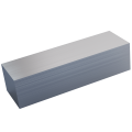
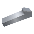
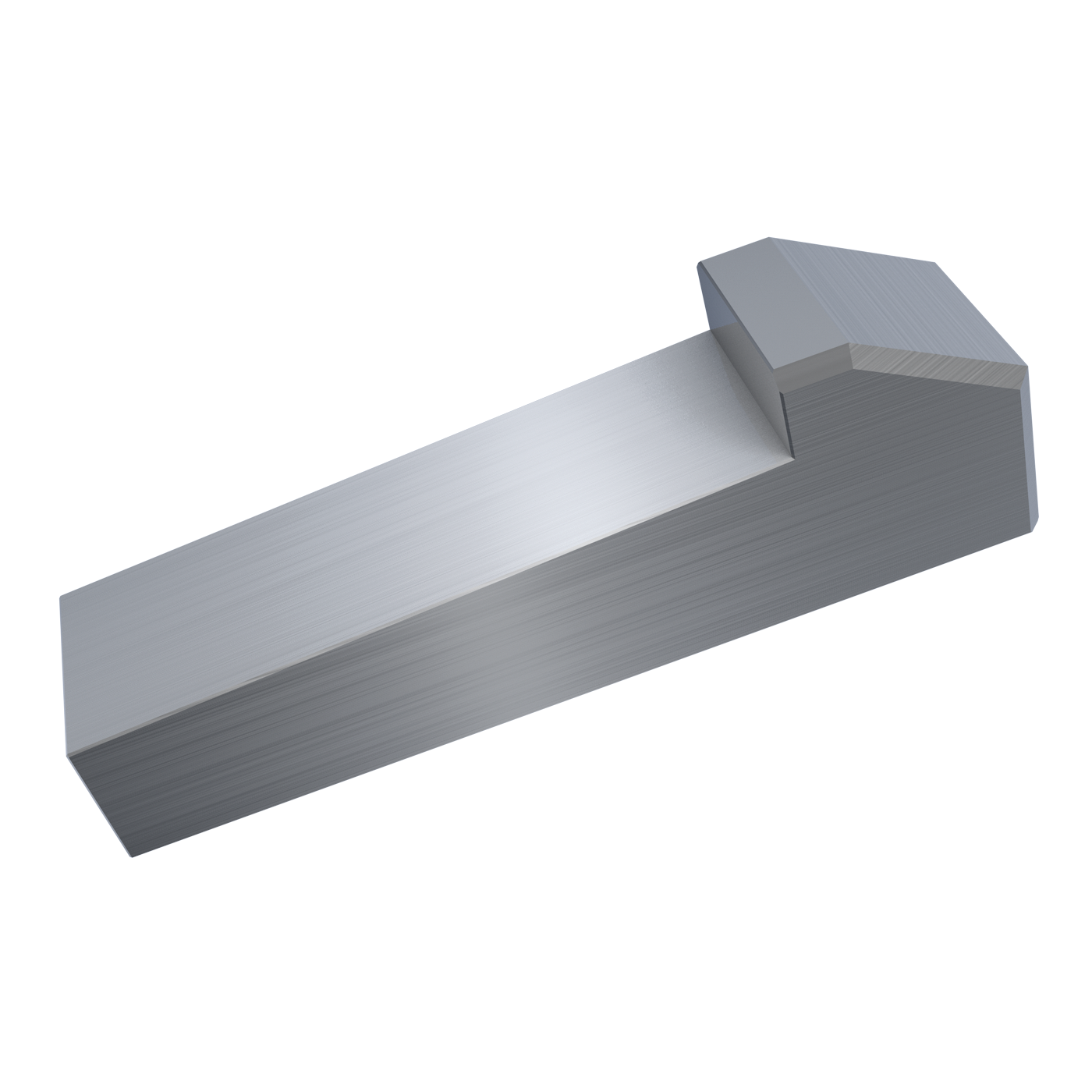
Taper key with gip head DIN 6887
Size
20x12x110
Material group
Steel
Surface
bright
Width b
20
Width b Tolerance
h9
Height h
12
for shaft Ø d¹ above
65
for shaft Ø d¹ up to
75
Key height h1
12,2
Key height h1 permiss. diff.
-0,2
Gip height h2
20
Shaft groove width b D10
20
Shaft groove depth t1
7,5
Shaft groove depth t1 permiss. diff.
+0,2
Hub groove depth t2²
3,9
Hub groove depth t2 permiss. diff.
+0,2
Bevelled/Rounded r1 min.
0,6
Bevelled/Rounded r1 max.
0,8
Rounding of groove bottom r2 max.
0,6
Rounding of groove bottom r2 min.
0,4
Length l³
110
Length l permiss. diff.
-0,3 -0,5
Material
Steel St 60-1 or key steel 1.0503 (C45K) according to DIN 6880
CAD file download
Format selection
